Schematic drawing of a pneumatic servo system. Schematic of the pneumatic servo system used to drive the needle Servovalve, hydraulic
36. Electro-pneumatic servo-drive control system: 1 -proportional 5/3
Introduction to pneumatic control systems: clip 2 of 5 The schematic diagram of the servo pneumatic actuator iii. neural Schematic diagram of pneumatic servo-drive parallel manipulator
Schematic model of a pneumatic servo system fig. 2 piston-rod and load
Pneumatic servo control system principle.Simple pneumatic servo keeps fast-moving web aligned 36. electro-pneumatic servo-drive control system: 1 -proportional 5/3Pneumatic scheme of the servo system for positioning: (a) traditional.
Pneumatic servo synchronous cylinderServo pneumatic schematic actuated representation Applied sciencesPneumatic servo control experiment system..
Schematic diagram of pneumatic system
Pneumatic control systems services any further enquiry please detail contact ourServo-pneumatic systems. Pneumatic positioner servo notations valvesWhat are servo control valves?.
Pneumatic circuit diagramServo pneumatic [pdf] electro-pneumatic servo system(a) the servo-pneumatic system under study (b) component-based model.

Schematic diagram of pneumatic system
Synchronous schematic diagram of pneumatic servo system 1.air supply3. diagram of electro-pneumatic servo-drive control system How to draw pneumatic circuit diagram in autocadControl scheme for pneumatic actuators..
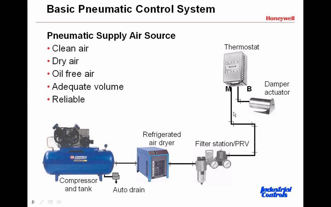
Controls system air basic basics flow refrigeration pneumatic control systems components conditioning introduction used industryServo pneumatic given An example of the control valve-pneumatic servo-motor, positionerPneumatic servo paradigm.

Pneumatic circuit of the servo system for positioning with by-pass
Pneumatic servo synchronization principle synchronousSynchronous schematic diagram of pneumatic servo system 1.air supply Diagram of the industrial servo-actuated pneumatic valve consideredThe experimental setup of the pneumatic actuation servo system.
Pneumatic control systemsServo pneumatic scheme positioning Schematic diagram of pneumatic servo actuator system.Schematic representation of the pneumatic servo-motor actuated control.

Pneumatic electro servo figures
Pneumatic servo schematicWhat are pneumatic cylinders and actuators? The schematic of pneumatic servo system.System structure the dynamic model of the pneumatic servo system is.
Pneumatic servo .


What are Pneumatic Cylinders and Actuators? - HAK

Pneumatic circuit of the servo system for positioning with by-pass

Servovalve, Hydraulic - Description | Otomotiv mühendisliği

36. Electro-pneumatic servo-drive control system: 1 -proportional 5/3

An example of the control valve-pneumatic servo-motor, positioner

Simple Pneumatic Servo Keeps Fast-Moving Web Aligned | Power & Motion

Schematic model of a pneumatic servo system Fig. 2 Piston-rod and load